Welcome: U-THERM INTERNATIONAL (H.K.) LIMITED


Introduction:
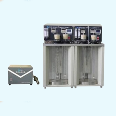
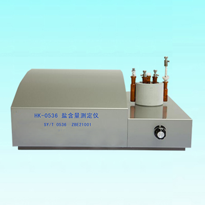
The instrument is used for the determination of evaporation loss of the lubricant and lubricant base oils.
How it works:
Sample is heated at a constant pressure of 250 ℃ and for 1h in evaporation loss tester, , evaporated oil vapor is carried out by the air . Quality difference of the samples was measured according to the evaporation loss of the sample before and after heating.
The whole structure:
The instrument is composed of two separate structures housing from heating device, vacuum regulator system, electrical control system: the main body and the regulator housing.
Heating device is provided in the upper part of the main body, is composed of the heating body, the evaporation crucible, crucible cover, heater, thermometer, sensors and others. Heating body is made of aluminum alloy, surrounded by tropical area, heating plate at bottom, outside insulation. Heating body center has a hole, to place evaporator crucible made of stainless steel, the crucible cover is made of brass, chrome appearance, and tight connection with crucible threaded. There are three holes in crucible cover made of hardened steel. Bent downward sloping intake pipe, with ferrule tightly fixed in the center of the crucible cover, the other end is connected with a hose and regulator bottles. Heater holes rear seat, set two equidistant additional holes, place a thermometer and sensors.
Electrical control system located in the lower part of the main body, composed of intelligent temperature controller, digital timer, switches and others.
Vacuum regulator system device is placed on the right side of the main body at 60mm from the body, composed of the regulator bottles, landing planes, vertical inclined tube manometer, trimming valves, pumps, tube and connecting hoses and others.
Both regulators bottles are placed on lifting frame abreast, each is free to lift. Oil and gas out of the intake pipe, through the Y-shaped glass bottle into the first regulator, out after by another glass bottle into the second regulator, and then out from the glass, by connection with fine-tuning valve and vacuum pump. (Fine valve is provided with emptying tube). The other end of Y type tube is connected to inclined tube manometer to form a stabilizing system.
All instruments are made of stainless steel, beautiful design, reasonable structure, easy to operate.
Technical Specifications
|
Description |
Parameters |
|
Power |
AC220V ± 20V, 50Hz |
|
Temperature control point |
250 ℃ |
|
Temperature accuracy |
± 0.5 ℃ |
|
The test hole |
Single hole |
|
The heating power |
600W, two groups |
|
The regulator bottle |
3L, two |
|
Inclined tube manometer |
196Pa ± 2 Pa (20mmH2O ± 0.2mmH2O |
|
Vacuum pump |
Negative values can be adjusted to 196 Pa pressure difference |
|
Ambient temperature |
Around room temperature 25 ℃ |
|
Relative humidity |
<85% RH |

 Send Email
 U-therm